What is it?
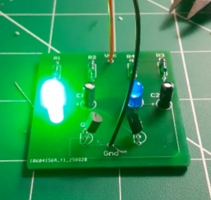
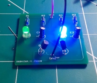
This is a PCB of a standard circuit: Astable Multivibrator. LEDs alternate, meaning that one is on and the other is off. This happens continuously, creating a blinking pattern.
How was this built?
Altium was used in the design process. First, a schematic was created. The schematic was then exported into the PCB editor. I used through-hole components and a via connected the ground plane on the bottom layer. After completing the layout, I exported Gerber and Drill files to a PCB manufacturer. Once the PCBs arrived, I soldered the components into the board.
Why was it built?
This project was created to develop proficiency in Altium and Soldering, both of which are industry-standard skills. Designing and soldering a simple PCB provided a hands-on way to gain experience.